
How to Choose Mould Components in 2026
Choosing the right Mould Components in 2026 requires more than comparing prices or copying an older tool design. Component selection affects cycle time, product accuracy, maintenance effort, and operator safety. A reliable decision begins with the mould’s purpose, material, expected production volume, and available machine capacity. It also requires practical knowledge of how components behave after thousands of cycles.
Small details matter. A guide bush with poor alignment can create uneven wear and flashing. An undersized ejector pin may bend when removing a deep, ribbed part. In contrast, properly matched steels, coatings, cooling fittings, and support elements can improve stability and extend service life. These choices should be checked against verified supplier data, technical drawings, tolerance requirements, and relevant industry standards. Experienced mould designers also review maintenance access before approving a component. Difficult replacement often becomes an expensive production problem.
No selection method is perfect. Real workshops face changing resin grades, rushed tooling schedules, and incomplete customer information. A component that performs well in one mould may fail in another. That is why trial results, inspection records, and feedback from mould technicians remain valuable. Do not trust a catalogue alone. Ask whether the component has suitable load ratings, dimensional consistency, corrosion resistance, and after-sales support. Careful comparison may take longer, but it reduces unexpected downtime. This guide explores practical criteria for choosing Mould Components in 2026, while recognizing that sound engineering still depends on testing, documentation, and honest review.
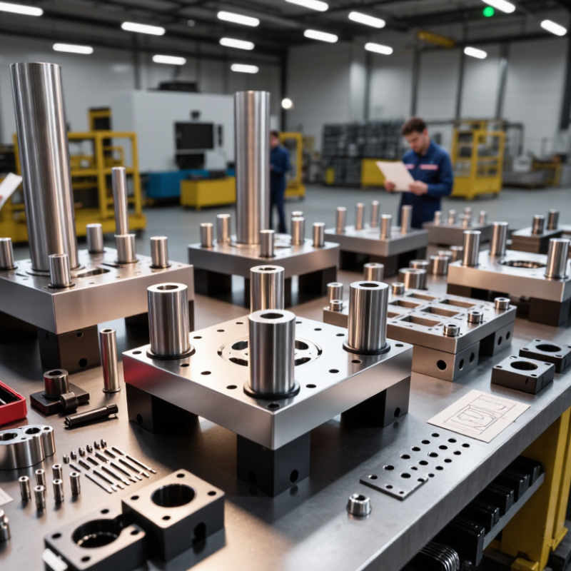
Defining Mould Requirements and Production Conditions
How to Choose Mould Components in 2026
Defining Mould Requirements and Production Conditions
Choosing mould components starts with the product, not the catalogue. Record the resin, part dimensions, wall thickness, tolerance, surface finish, and expected annual volume. A small connector and a large automotive cover need different support systems. They also create different cooling challenges.
Production conditions matter just as much. Check the injection machine’s clamp force, shot capacity, tie-bar spacing, and maximum mould height. Measure these details before selecting plates, guide systems, ejectors, or hot-runner components. A mould may fit the drawing but fail inside the press. That mistake is expensive.
Think about the factory floor. Is cooling water stable during long shifts? Can technicians replace an ejector without removing the mould? Does the steel resist the resin’s additives and repeated pressure? These practical questions often decide component life. I have seen designs with excellent tolerances perform poorly because venting was treated as an afterthought. Small vents can prevent burns, short shots, and long troubleshooting sessions.
Define maintenance conditions too. High-volume production may justify hardened wear surfaces and monitored cooling channels. Short-run work may need simpler, accessible components instead. Document inspection points, spare quantities, lubrication needs, and acceptable wear limits. Do not assume every supplier interprets tolerance symbols identically. Confirm critical dimensions with clear drawings and sample measurements. Some decisions will remain uncertain. That is normal. Use trial moulding data to revise the design, rather than defending an early assumption.
Selecting the Right Mould Base and Structural Layout
How to Choose Mould Components in 2026
Selecting the Right Mould Base and Structural Layout
A mould base should match the machine before it matches the product drawing. Check platen size, tie-bar spacing, clamping force, and maximum mould height. Leave enough room for cooling fittings and safe handling. A base that is too small may flex under pressure. A base that is oversized adds weight, cost, and slower setup.
The structural layout controls alignment, filling, cooling, and ejection. Place guide pillars away from weak corners, and support cavity plates near high-pressure areas. Keep ejector pins behind strong sections of the part, not thin cosmetic surfaces. For complex parts, a three-plate layout may improve gate control, but it also increases maintenance. Simpler is often safer.
Measure twice.
During design reviews, I compare cavity pressure estimates with plate thickness and support spacing. Steel selection should consider wear, corrosion, polishing needs, and production volume. Cooling channels need practical drill access, not just attractive lines on a screen. I once approved a compact layout that saved material but left little space for cleaning. It worked, yet servicing became frustrating. That mistake changed my checklist. I now inspect tool access, lifting points, spare component space, and assembly sequence before release. Simulation can reveal risks, but workshop feedback remains essential. Some layouts still need revision after the first trial.
How to Choose Mould Components in 2026: Selecting the Right Mould Base and Structural Layout
This comparison shows representative room-temperature values for commonly used mould materials. Higher thermal conductivity can support faster and more uniform cooling, while higher hardness can improve resistance to wear and deformation. Final component selection should also consider corrosion exposure, moulding pressure, machining requirements, heat treatment, and the stiffness of the overall structural layout.
Values are typical midpoint figures from published material-property ranges; exact performance varies by grade, heat treatment, supplier specification, and operating temperature.
Comparing Materials for Cores, Cavities, and Inserts
How to Choose Mould Components in 2026
Comparing materials for cores, cavities, and inserts starts with heat, pressure, and production volume. Tool steel remains the safer choice for high-cycle cores and cavities. Its hardness supports repeated clamping and ejection. The World Steel Association reported 1.89 billion tonnes of crude steel production in 2023. That scale supports broad availability and easier replacement sourcing.
Cavities need polishability, corrosion resistance, and dimensional stability. Pre-hardened steel can reduce machining time for moderate volumes. Hardened stainless steel suits glass-filled polymers or humid processing environments. However, “stainless” does not automatically mean better. Its higher cost may bring little value in a short production run. According to the ASM Handbook, copper alloys can conduct heat several times faster than conventional tool steels. They work well as inserts around deep ribs, sharp corners, and hot spots. The 2024 USGS Mineral Commodity Summaries recorded about 22 million metric tonnes of global mined copper output in 2023, supporting a mature supply chain.
A practical design may combine hardened steel with copper alloy inserts. Keep the insert compact and mechanically locked. Avoid placing it where repeated impact can cause deformation. I would not choose materials from hardness charts alone. Cooling layout, resin additives, wall thickness, and maintenance often change the result. The weak point is prediction. A short mould trial can reveal burrs, thermal imbalance, or unexpected polishing damage before full production.
How to Choose Mould Components in 2026 - Comparing Materials for Cores, Cavities, and Inserts
Practical material comparison for injection moulding applications
| Material family / typical grade | Typical hardness | Thermal conductivity | Wear resistance | Corrosion resistance | Machinability | Best-suited mould component | Recommended use case |
|---|---|---|---|---|---|---|---|
| Pre-hardened plastic mould steel Typical grade: P20 / 1.2311 | Approximately 28–36 HRC | Approximately 29–34 W/m·K | Moderate | Low; requires protection in humid environments | Good; suitable for conventional milling and drilling | Large cores, cavities, mould bases and plates | General-purpose moulds for non-abrasive thermoplastics and medium production volumes |
| Pre-hardened stainless mould steel Typical grade: 1.2083 / 420 stainless steel | Approximately 45–52 HRC after hardening | Approximately 20–25 W/m·K | Good | Good when properly heat-treated and polished | Fair to moderate; slower cutting and careful polishing are required | Cavities, cores and inserts exposed to moisture or corrosive resin | Medical, optical, food-contact and moulding applications using PVC or flame-retardant materials |
| Hot-work tool steel Typical grade: H13 / 1.2344 | Approximately 44–52 HRC | Approximately 24–30 W/m·K | Very good | Low to moderate; surface treatment may be needed | Moderate; carbide tooling and controlled heat treatment improve results | High-wear cores, cavities and hot-runner components | Glass-filled polymers, high moulding temperatures and long production runs |
| Maraging steel Typical grade: 18Ni maraging steel | Approximately 48–54 HRC after ageing | Approximately 20–25 W/m·K | Very good | Moderate; not equivalent to stainless steel | Good before ageing; considerably harder to machine after ageing | Precision inserts, thin ribs and components requiring high dimensional stability | High-precision moulds, complex textures and additive-manufactured inserts requiring post-machining |
| Powder metallurgy tool steel Typical grade: high-chromium PM steel | Approximately 58–64 HRC | Approximately 20–30 W/m·K | Excellent | Low to moderate, depending on alloy composition and finish | Difficult; EDM, grinding and carbide tooling are commonly used | Replaceable wear inserts and high-abrasion cavity sections | Glass-fibre, mineral-filled or flame-retardant compounds with severe abrasive wear |
| Beryllium copper alloy Typical grade: CuBe2 | Approximately 35–44 HRC after age hardening | Approximately 105–130 W/m·K | Moderate to good | Good in typical moulding environments | Good, although machining dust requires strict occupational controls | Cooling inserts, cores and hot-spot sections | Deep ribs, bosses and areas where rapid heat removal reduces cycle time or warpage |
| Copper alloy without beryllium Typical grade: precipitation-hardened Cu-Ni-Si or Cu-Cr-Zr | Approximately 28–45 HRC, depending on alloy and treatment | Approximately 150–300 W/m·K | Moderate | Good | Good to very good | Thermal inserts and conformal-cooling components | Applications requiring high heat transfer while avoiding beryllium exposure |
| Tungsten carbide Typical grade: cemented carbide | Approximately 1,000–1,700 HV | Approximately 50–110 W/m·K, depending on binder content | Excellent | Good in most polymer-processing environments | Poor by conventional methods; grinding and EDM are typical | Small wear inserts, gates, valve seats and high-pressure sealing areas | Extremely abrasive compounds, high-volume production and erosion-prone details |
| Tool steel with surface coating Typical treatment: nitriding, PVD or duplex treatment | Base steel typically 40–60 HRC; coated surface may exceed 1,000 HV | Usually close to the base steel; thin coatings have limited thermal effect | Very good to excellent, depending on coating and counterface | Improved surface protection, but coating defects can expose the substrate | Machining is performed before coating; repair and recoating require process control | Cores, cavities and inserts requiring lower friction or improved release | Abrasive resins, sliding details, difficult-release parts and extended maintenance intervals |
Choosing Ejection, Cooling, and Guiding Components
How to Choose Mould Components in 2026
Choosing Ejection, Cooling, and Guiding Components
A reliable mould starts with the part’s release, heat flow, and movement. Ejection pins should support strong areas, not thin ribs or visible surfaces. Place them symmetrically when possible. This reduces white marks, distortion, and uneven release. For deep parts, sleeves or lifting plates may distribute force more evenly. Short stroke tests can reveal problems before full production.
Cooling channels need practical spacing around thick sections, corners, and inserts. Keep the circuit balanced, rather than forcing one long path through the entire mould. Measure inlet and outlet temperatures during trials. A small temperature difference can expose a blocked passage or poor flow. I have seen cycle times increase because a cooling layout looked tidy but ignored a heavy boss. The drawing was correct. The result was not.
Guiding components protect alignment during closing. Use guide posts, bushes, and locating features according to mould size, load, and expected wear. Check clearance after assembly, not only from the CAD model. Dirt, heat, and repeated impact can change performance. Fit matters. Measure twice. In practice, designers sometimes over-specify guides while underestimating ejection force. That mistake adds cost without solving flash or part sticking. Review contact marks after the first trial, then adjust one variable at a time. A mould should be serviceable, measurable, and forgiving when production conditions are less than perfect.
Checking Compatibility, Maintenance, Cost, and Future Upgrades
How to Choose Mould Components in 2026
Compatibility should be checked before price. Confirm dimensions, mounting holes, cooling channels, ejector alignment, steel grade, and surface treatment. A 0.02 mm mismatch can create flash, uneven wear, or difficult maintenance. Record these details in a component register. It helps technicians replace parts without guessing.
Maintenance access matters. Choose components that can be inspected without removing half the mould. Standardized inserts, visible wear indicators, and accessible lubrication points reduce service time. Keep spare parts for high-wear areas, not every possible failure. This is less expensive.
However, adding sensors without a clear decision process can create noise. I have seen teams collect data they never review. That mistake deserves attention.
Calculate total cost across the expected production life. Include tooling changes, downtime, cleaning, spare parts, energy use, and technician hours. A cheaper component may become expensive after repeated stoppages.
Leave physical space for upgraded cooling lines, sensors, or faster ejection systems. Future upgrades need clearance, compatible interfaces, and documented tolerances. Do not assume tomorrow’s technology will fit today’s layout.
